SUPERIOR CONVEYOR TECHNICIANS
Installation and maintenance
Correct set-out, secure components and even contact protect the belt. Inspect the complete cleaner, not just the wearing parts.
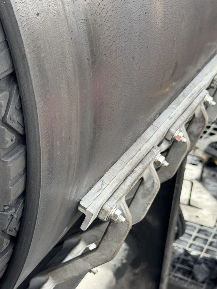
INSTALLATION CONTROL
Primary Head Cleaner coordinates
Verify X, Y and C before setting tip angle and tension.
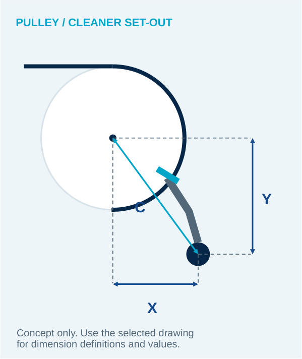
Use the correct datum
Establish the head-pulley centreline and measure the finished diameter over the belt and lagging. Confirm the selected suspension-arm size before marking the mounts.
Check both sides
Take X, Y and C from the installation drawing for the exact assembly. Record the measurements on both chute walls and verify pole alignment before fixing the mounting brackets.
Set tips after the pole position
Align and secure the tips, check arm and cushion movement, then set the specified tension. Changing arm size, tip profile or pole position requires another geometry check.
Mounting, tensioning and access
Qualified installation and servicing
Use qualified conveyor technicians familiar with the cleaner being fitted. Poor geometry, unsecured tips, seized cushions or excessive contact pressure can damage the belt cover or splice.
Set tension to a defined value
Identify the spring, air system or mechanical adjuster. Use its specified preload, compressed spring length or pressure. Record the setting; a number of turns copied from another cleaner is not a reliable reference.
Support and removal space
Check the mounting steelwork, pole or mainframe span and the service side. The cleaner needs clearance through adjustment and a safe removal path after isolation.
Pressure rollers
A suitable support arrangement can steady the belt at a residual-cleaning position. Confirm roller alignment and match the mounts to the roller shaft-end fit.
FAULT IDENTIFICATION
Tip failure and belt damage
Identify the failed component and inspect the belt before restarting.
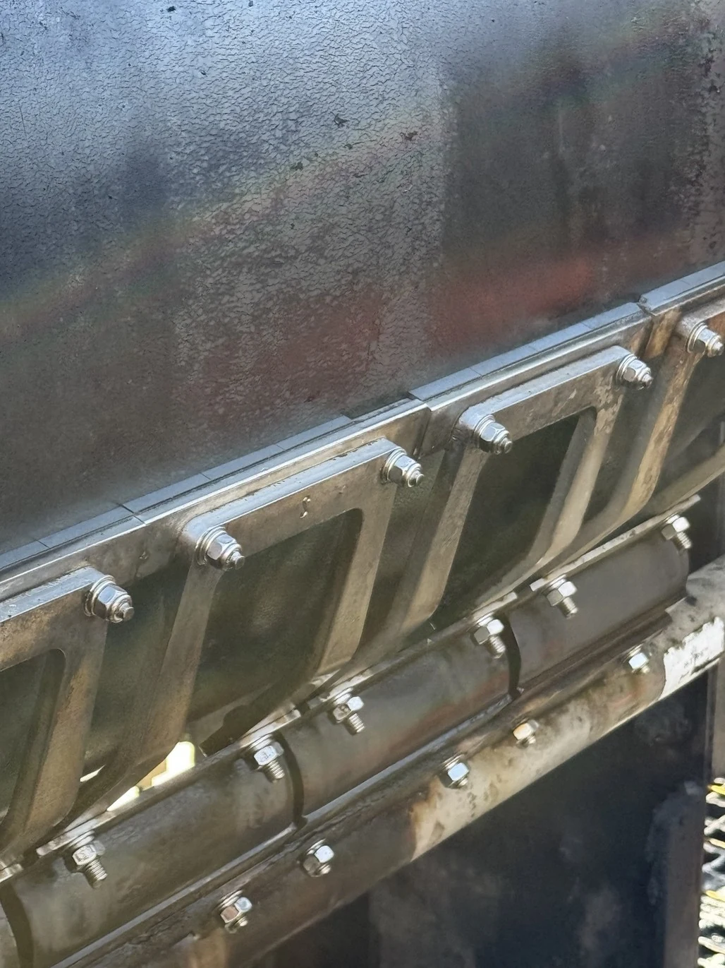
Inspect the complete support
Inspect the tip, attachment and suspension arm together. Check adjacent segments, cushion movement and damage along the belt path.
Corrective work
Isolate the conveyor and make the failed cleaner safe. Replace damaged components, restore retention and alignment, then verify the complete set-out and tension before recommissioning.
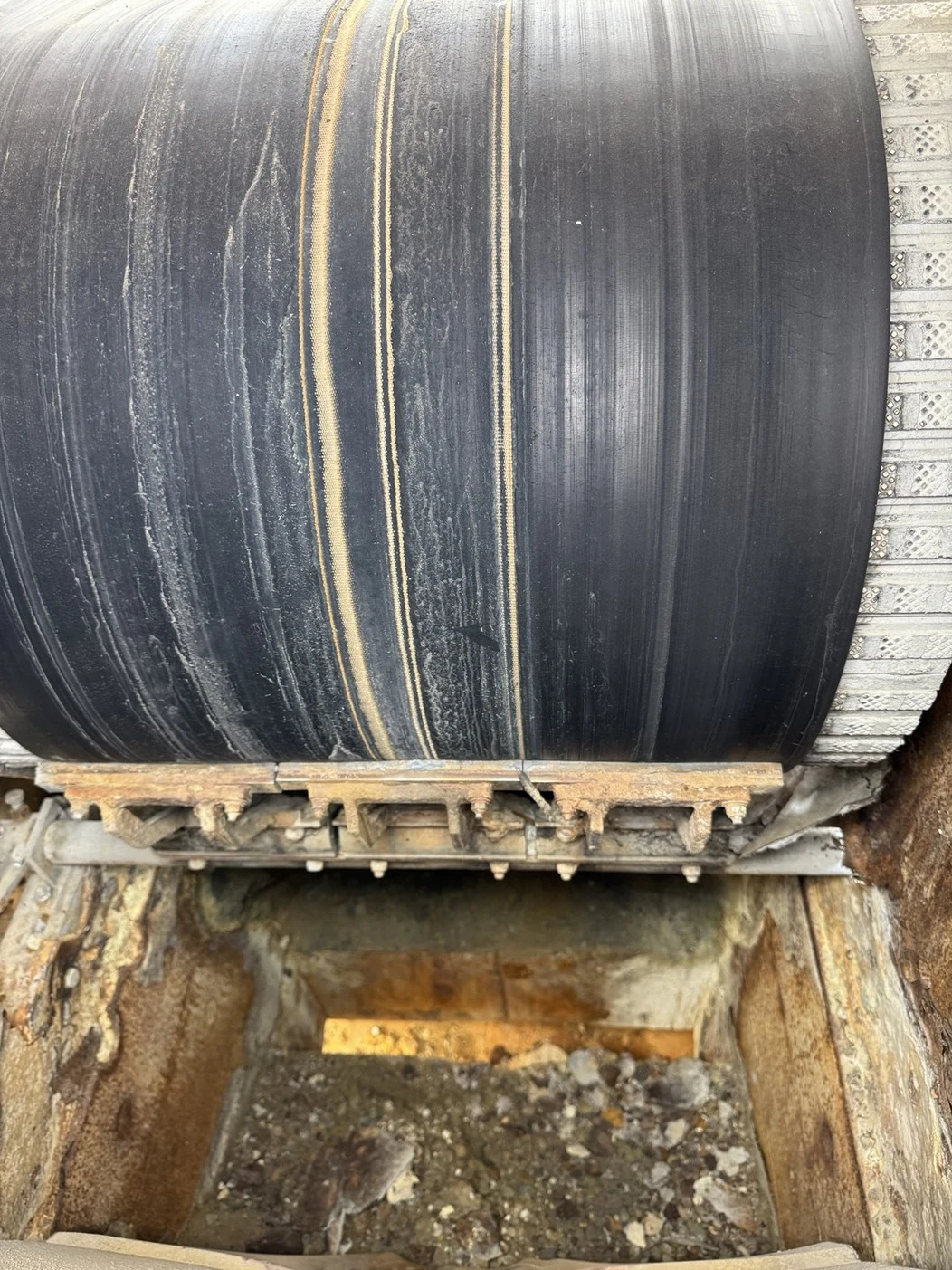
Damaged belt cover
Assess the depth and extent of damage, the splice and the condition of every tip or blade. Do not treat a grooved cover as a simple tensioning problem.
Check the cause on site
Record tip edges, wear heights, retention, cushion condition, contact angle and pole position. Establish the cause from the full inspection rather than tightening the cleaner against an already damaged belt.
INSPECTION AND MAINTENANCE
Cushions and material build-up
Wear-part replacement alone will not restore a failed support system.
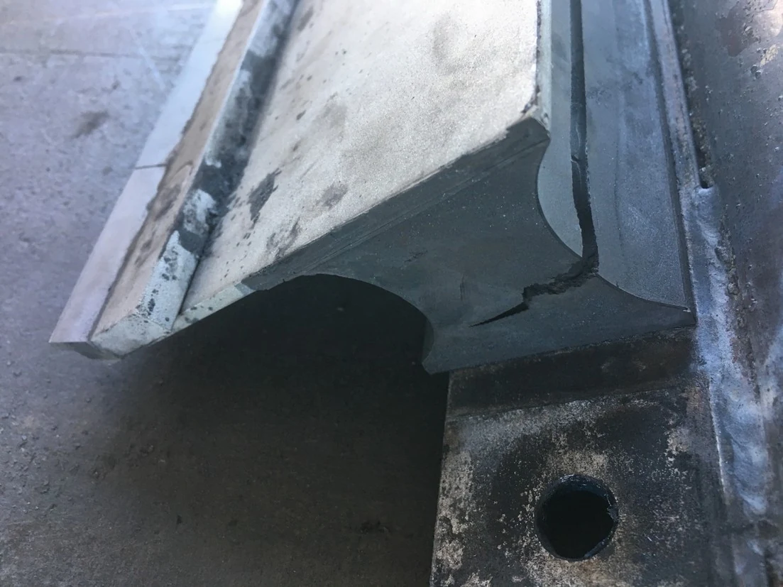
Cracked or separated cushion
Inspect the body, bonded interfaces and attachments. Check adjacent cushions rather than assuming damage is confined to one position. A new tungsten tip will still be poorly supported by a failed cushion.
Reset after replacement
Fit the correct cushion and attachment parts, restore tip alignment and verify tension. Check the working movement and follow up after the cleaner has bedded in.
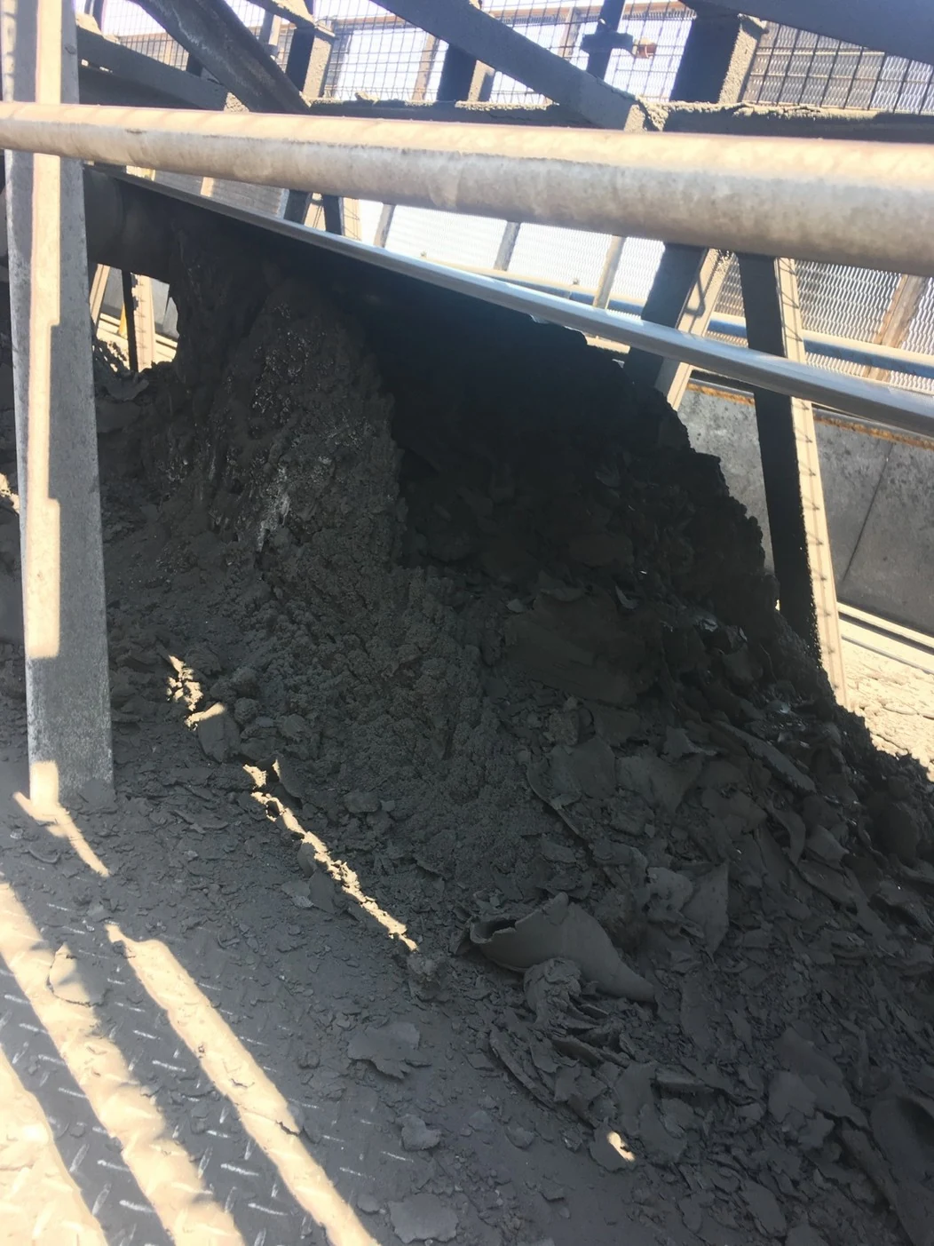
Material trapped around the cleaner
Build-up can hide fasteners, restrict movement and prevent removed product leaving the cleaning zone. Inspect chute clearance, drainage, access and the performance of earlier cleaning stages.
Restore access and containment
Clear accumulated product under site controls, identify where it is coming from and correct the discharge path. Keep inspection points and the component-removal route accessible.
COMMISSIONING AND HANDOVER
Record condition, not just replacement dates
A useful service record includes the cleaner configuration, work completed, tip or blade wear, support condition, settings, belt damage and the next corrective action.
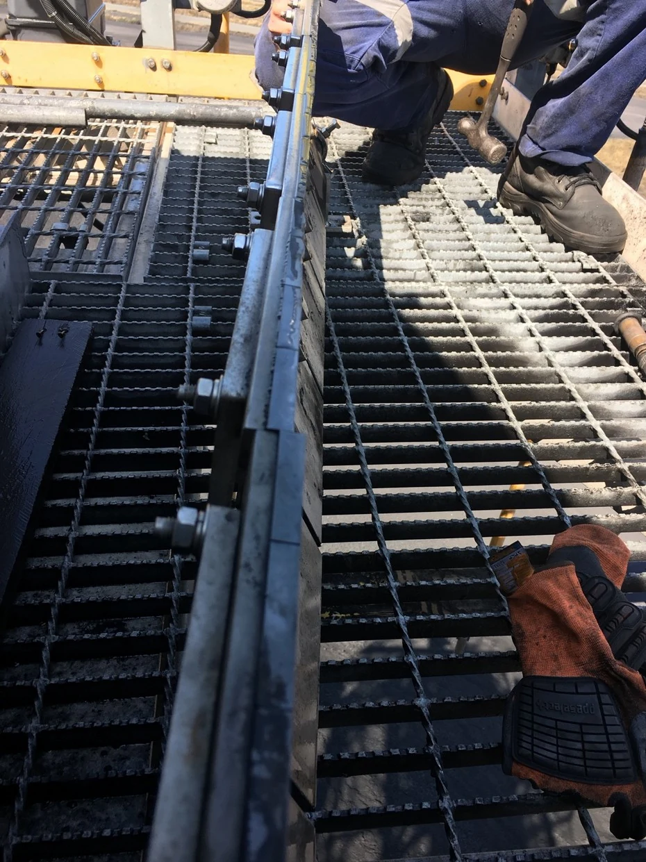
Observe from protected, authorised positions. Record settings, photos, outstanding defects and the next inspection requirements.
Arrange cleaner servicing
Conveyor maintenance, belt repairs, workshop refurbishment and component supply.
Based in Paget, Mackay. Site support across the Bowen Basin and surrounding regions.
Services
Mechanical maintenanceBelt splicing & rubberWorkshop & refurbishmentInspections & monitoringBelt tracking inspectionsProducts
Rollers — Steel / HDPE / UHMWPEBelt cleaning systemsConveyor pulleys & laggingRubber gasketsConveyor beltProduct enquiriesContact & information
0417 363 878admin@superiorconveyors.com.au45–47 Centurion Drive
Paget QLD 4740